
These are notes I made while completing JITL‘s Megalab. You can follow along by watching this video and grabbing the PKA file in the description.
I certainly don’t own anything I’ve posted here, which are excerpts from JITL’s PKA file, and Wendell Odom’s books CCNA 200-301: Official Cert Guide, 1st edition vol 1 and vol 2.
Spoiler warning, these notes contain configs.
Last post handled exclusively layer 2 content. This post is going to focus on layer 3. This section in particular is pretty long and repetitive. Careful not to lose your place while configuring each IP address.
- Configure the following IP addresses on R1’s interfaces and enable them:
- G0/0/0: DHCP client
- G0/1/0: DHCP client
- G0/0: 10.0.0.33/30
- G0/1: 10.0.0.37/30
- Loopback0: 10.0.0.76/32
DHCP can be enabled with ip address dhcp when in interface config mode.
! R1
int range g0/0/0,g0/1/0
ip address dhcp
!
int g0/0
ip add 10.0.0.33 255.255.255.252
!
int g0/1
ip add 10.0.0.37 255.255.255.252
!
int lo0
ip add 10.0.0.76 255.255.255.255- Enable IPv4 routing on all Core and Distribution switches.
This is done with the ip routing global config command.
- Create a Layer-3 EtherChannel between CSW1 and CSW2 using a Cisco-proprietary protocol. Both switches should actively try to form an EtherChannel. Configure the following IP addresses:
- CSW1 PortChannel1: 10.0.0.41/30
- CSW2 PortChannel1: 10.0.0.42/30
This one can be tricky. When you create a portchannel interface, it’s created as L2 or L3 depending on what interfaces are included. For L3, make sure to disable switching on these interfaces with no switchport first.
! CSW1
! which interfaces?
CSW1(config)#do show cdp nei
Capability Codes: R - Router, T - Trans Bridge, B - Source Route Bridge
                  S - Switch, H - Host, I - IGMP, r - Repeater, P - Phone
Device ID    Local Intrfce   Holdtme    Capability   Platform    Port ID
DSW-B2       Gig 1/1/4        172                    3650        Gig 1/1/1
DSW-B1       Gig 1/1/3        172                    3650        Gig 1/1/1
CSW2         Gig 1/0/2        172                    3650        Gig 1/0/2
CSW2         Gig 1/0/3        172                    3650        Gig 1/0/3
DSW-A2       Gig 1/1/2        172                    3650        Gig 1/1/1
DSW-A1       Gig 1/1/1        172                    3650        Gig 1/1/1
We’re interested in g1/0/2-3.
! CSW1
int range g1/0/2-3
no switchport     ! important
channel-group 1 mode desirable
!
int po1
ip address 10.0.0.41 255.255.255.252
And repeat for CWS2 with 10.0.0.42 255.255.255.252
Let’s verify it worked.
CSW1(config-if)#do show etherchannel sum
Flags:  D - down        P - in port-channel
        I - stand-alone s - suspended
        H - Hot-standby (LACP only)
        R - Layer3      S - Layer2
        U - in use      f - failed to allocate aggregator
        u - unsuitable for bundling
        w - waiting to be aggregated
        d - default port


Number of channel-groups in use: 1
Number of aggregators:           1

Group  Port-channel  Protocol    Ports
------+-------------+-----------+----------------------------------------------

1 Po1(RU) PAgP Gig1/0/2(P) Gig1/0/3(P)- Configure the following IP addresses on CSW1. Disable all unused interfaces.
- G1/0/1: 10.0.0.34/30
- G1/1/1: 10.0.0.45/30
- G1/1/2: 10.0.0.49/30
- G1/1/3: 10.0.0.53/30
- G1/1/4: 10.0.0.57/30
- Loopback0: 10.0.0.77/32
Moving on, some easy steps. Nothing we haven’t seen before.
! CSW1
int g1/0/1
no switchport
ip add 10.0.0.34 255.255.255.252
!
int g1/1/1
no switchport
ip add 10.0.0.45 255.255.255.252
!
int g1/1/2
no switchport
ip add 10.0.0.49 255.255.255.252
!
int g1/1/3
no switchport
ip add 10.0.0.53 255.255.255.252
!
int g1/1/4
no switchport
ip add 10.0.0.57 255.255.255.252
!
int lo0
ip add 10.0.0.77 255.255.255.255
!
int range g1/0/4-24
shut
What happens if we forget the no switchport ? IOS simply doesn’t allow this. You have to disable switching before you can assign a L3 address. Neat!
CSW2(config)#int g1/0/1
CSW2(config-if)#ip add 10.0.0.38 255.255.255.252
                    ^
% Invalid input detected at '^' marker. - Configure the following IP addresses on CSW2. Disable all unused interfaces.
- G1/0/1: 10.0.0.38/30
- G1/1/1: 10.0.0.61/30
- G1/1/2: 10.0.0.65/30
- G1/1/3: 10.0.0.69/30
- G1/1/4: 10.0.0.73/30
- Loopback0: 10.0.0.78/32
! CSW2
int g1/0/1
no switchport
ip add 10.0.0.38 255.255.255.252
!
int g1/1/1
no switchport
ip add 10.0.0.61 255.255.255.252
!
int g1/1/2
no switchport
ip add 10.0.0.65 255.255.255.252
!
int g1/1/3
no switchport
ip add 10.0.0.69 255.255.255.252
!
int g1/1/4
no switchport
ip add 10.0.0.73 255.255.255.252
!
int lo0
ip add 10.0.0.78 255.255.255.255
!
int range g1/0/4-24
shut- Configure the following IP addresses on DSW-A1:
- G1/1/1: 10.0.0.46/30
- G1/1/2: 10.0.0.62/30
- Loopback0: 10.0.0.79/32
! DSW-A1

int g1/1/1
no switchport
ip add 10.0.0.46 255.255.255.252
!
int g1/1/2
no switchport
ip add 10.0.0.62 255.255.255.252
!
int lo0
ip add 10.0.0.79 255.255.255.255- Configure the following IP addresses on DSW-A2:
- G1/1/1: 10.0.0.50/30
- G1/1/2: 10.0.0.66/30
- Loopback0: 10.0.0.80/32
! DSW-A2

int g1/1/1
no switchport
ip add 10.0.0.50 255.255.255.252
!
int g1/1/2
no switchport
ip add 10.0.0.66 255.255.255.252
!
int lo0
ip add 10.0.0.80 255.255.255.255- Configure the following IP addresses on DSW-B1:
- G1/1/1: 10.0.0.54/30
- G1/1/2: 10.0.0.70/30
- Loopback0: 10.0.0.81/32
! DSW-B1

int g1/1/1
no switchport
ip add 10.0.0.54 255.255.255.252
!
int g1/1/2
no switchport
ip add 10.0.0.70 255.255.255.252
!
int lo0
ip add 10.0.0.81 255.255.255.255- Configure the following IP addresses on DSW-B2:
- G1/1/1: 10.0.0.58/30
- G1/1/2: 10.0.0.74/30
- Loopback0: 10.0.0.82/32
! DSW-B2

int g1/1/1
no switchport
ip add 10.0.0.58 255.255.255.252
!
int g1/1/2
no switchport
ip add 10.0.0.74 255.255.255.252
!
int lo0
ip add 10.0.0.82 255.255.255.255
Getting sleepy yet? Me too.
Another interesting bit, loopback interfaces can’t be switchports, so the switchport commands aren’t even available for use.
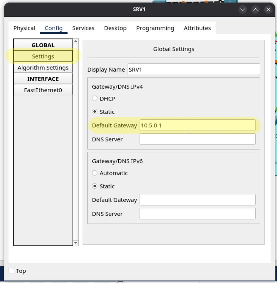
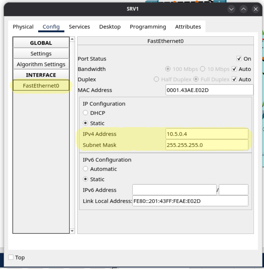
- Manually configure SRV1’s IP settings:
- Default Gateway: 10.5.0.1
- IPv4 Address: 10.5.0.4
- Subnet Mask: 255.255.255.0
Nothing in CLI to do here. Click on the server in PacketTracer and input all this info.
- Configure the following management IP addresses on the Access switches (interface VLAN 99), and configure the appropriate subnet’s first usable address as the default gateway.
- ASW-A1: 10.0.0.4/28
- ASW-A2: 10.0.0.5/28
- ASW-A3: 10.0.0.6/28
- ASW-B1: 10.0.0.20/28
- ASW-B2: 10.0.0.21/28
- ASW-B3: 10.0.0.22/28
/28 leaves us 4 bits, which is 16 addresses. Need a refresher on subnetting?
! ASW-A1
ip default-gateway 10.0.0.1
int vlan 99
ip add 10.0.0.4 255.255.255.240
!
! ASW-A2
ip default-gateway 10.0.0.1
int vlan 99
ip add 10.0.0.5 255.255.255.240
!
! ASW-A3
ip default-gateway 10.0.0.1
int vlan 99
ip add 10.0.0.6 255.255.255.240
!
! ASW-B1
ip default-gateway 10.0.0.17
int vlan 99
ip add 10.0.0.20 255.255.255.240
!
! ASW-B2
ip default-gateway 10.0.0.17
int vlan 99
ip add 10.0.0.21 255.255.255.240
!
! ASW-B3
ip default-gateway 10.0.0.17
int vlan 99
ip add 10.0.0.22 255.255.255.240- Configure HSRPv2 group 1 for Office A’s Management subnet (VLAN 99). Make DSW-A1 the Active router by increasing its priority to 5 above the default, and enable preemption on DSW-A1.
- Subnet: 10.0.0.0/28
- VIP: 10.0.0.1
- DSW-A1: 10.0.0.2
- DSW-A2: 10.0.0.3
Now onto the interesting part. Hot Swap Routing Protocol (HSRP) allows two L3 devices to share an virtual IP address. When the active router goes down, the spare router takes its place seamlessly. Configuring HSRP is not on the CCNA 201-301 v1.1 exam, but describing why it’s important is. Let’s tackle it anyways because it’s not that difficult.
3.5 Describe the purpose, functions, and concepts of first hop redundancy protocols1
You might see some errors saying “Duplicate IP Address” when setting up HSRP. Write your changes and reload both routers to fix.
! DSW-A1
int vlan 99
ip address 10.0.0.2 255.255.255.240
standby version 2
standby 1 ip 10.0.0.1
standby 1 priority 105
standby 1 preempt

! DSW-A2
int vlan 99
ip address 10.0.0.3 255.255.255.240
standby version 2
standby 1 ip 10.0.0.1- Configure HSRPv2 group 2 for Office A’s PCs subnet (VLAN 10). Make DSW-A1 the Active router by increasing its priority to 5 above the default, and enable preemption on DSW-A1.
- Subnet: 10.1.0.0/24
- VIP: 10.1.0.1
- DSW-A1: 10.1.0.2
- DSW-A2: 10.1.0.3
! DSW-A1
int vlan 10
ip address 10.1.0.2 255.255.255.0
standby version 2
standby 2 ip 10.1.0.1
standby 2 priority 105
standby 2 preempt

! DSW-A2
int vlan 10
ip address 10.1.0.3 255.255.255.0
standby version 2
standby 2 ip 10.1.0.1- Configure HSRPv2 group 3 for Office A’s Phones subnet (VLAN 20). Make DSW-A2 the Active router by increasing its priority to 5 above the default, and enable preemption on DSW-A2.
- Subnet: 10.2.0.0/24
- VIP: 10.2.0.1
- DSW-A1: 10.2.0.2
- DSW-A2: 10.2.0.3
Notice DSW-A2 is the Active router now. Making different routers active for different vlans is a way of load-balancing network traffic.
! DSW-A2
int vlan 20
ip address 10.2.0.3 255.255.255.0
standby version 2
standby 3 ip 10.2.0.1
standby 3 priority 105
standby 3 preempt

! DSW-A1
int vlan 20
ip address 10.2.0.2 255.255.255.0
standby version 2
standby 3 ip 10.2.0.1- Configure HSRPv2 group 4 for Office A’s Wi-Fi subnet (VLAN 40). Make DSW-A2 the Active router by increasing its priority to 5 above the default, and enable preemption on DSW-A2.
- Subnet: 10.6.0.0/24
- VIP: 10.6.0.1
- DSW-A1: 10.6.0.2
- DSW-A2: 10.6.0.3
! DSW-A2
int vlan 40
ip address 10.6.0.3 255.255.255.0
standby version 2
standby 4 ip 10.6.0.1
standby 4 priority 105
standby 4 preempt

! DSW-A1
int vlan 40
ip address 10.6.0.2 255.255.255.0
standby version 2
standby 4 ip 10.6.0.1- Configure HSRPv2 group 1 for Office B’s Management subnet (VLAN 99). Make DSW-B1 the Active router by increasing its priority to 5 above the default, and enable preemption on DSW-B1.
- Subnet: 10.0.0.16/28
- VIP: 10.0.0.17
- DSW-B1: 10.0.0.18
- DSW-B2: 10.0.0.19
! DSW-B1
int vlan 99
ip address 10.0.0.18 255.255.255.240
standby version 2
standby 1 ip 10.0.0.17
standby 1 priority 105
standby 1 preempt

! DSW-B2
int vlan 99
ip address 10.0.0.19 255.255.255.240
standby version 2
standby 1 ip 10.0.0.17- Configure HSRPv2 group 2 for Office B’s PCs subnet (VLAN 10). Make DSW-B1 the Active router by increasing its priority to 5 above the default, and enable preemption on DSW-B1.
- Subnet: 10.3.0.0/24
- VIP: 10.3.0.1
- DSW-B1: 10.3.0.2
- DSW-B2: 10.3.0.3
! DSW-B1
int vlan 10
ip address 10.3.0.2 255.255.255.0
standby version 2
standby 2 ip 10.3.0.1
standby 2 priority 105
standby 2 preempt

! DSW-B2
int vlan 10
ip address 10.3.0.3 255.255.255.0
standby version 2
standby 2 ip 10.3.0.1- Configure HSRPv2 group 3 for Office B’s Phones subnet (VLAN 20). Make DSW-B2 the Active router by increasing its priority to 5 above the default, and enable preemption on DSW-B2.
- Subnet: 10.4.0.0/24
- VIP: 10.4.0.1
- DSW-B1: 10.4.0.2
- DSW-B2: 10.4.0.3
! DSW-B2
int vlan 20
ip address 10.4.0.3 255.255.255.0
standby version 2
standby 3 ip 10.4.0.1
standby 3 priority 105
standby 3 preempt

! DSW-B1
int vlan 20
ip address 10.4.0.2 255.255.255.0
standby version 2
standby 3 ip 10.4.0.1- Configure HSRPv2 group 4 for Office B’s Servers subnet (VLAN 30). Make DSW-B2 the Active router by increasing its priority to 5 above the default, and enable preemption on DSW-B2.
- Subnet: 10.5.0.0/24
- VIP: 10.5.0.1
- DSW-B1: 10.5.0.2
- DSW-B2: 10.5.0.3
! DSW-B2
int vlan 30
ip address 10.5.0.3 255.255.255.0
standby version 2
standby 4 ip 10.5.0.1
standby 4 priority 105
standby 4 preempt

! DSW-B1
int vlan 30
ip address 10.5.0.2 255.255.255.0
standby version 2
standby 4 ip 10.5.0.1
That was a ton of work. In my opinion, it’s best to write your configs in a text editor, then copy and paste them into terminal to avoid any typos.
Let’s verify all that HSRP config now.
DSW-A1(config-if)#do show standby brief
                     P indicates configured to preempt.
                     |
Interface   Grp  Pri P State    Active          Standby         Virtual IP
Vl10        2    105 P Active   local           10.1.0.3        10.1.0.1
Vl99        1    105 P Active   local           10.0.0.3        10.0.0.1
Vl20        3    100   Standby  10.2.0.3        local           10.2.0.1
Vl40        4    100   Standby  10.6.0.3        local           10.6.0.1


DSW-A2(config-if)#do show standby brief
                     P indicates configured to preempt.
                     |
Interface   Grp  Pri P State    Active          Standby         Virtual IP
Vl10        2    100   Standby  10.1.0.2        local           10.1.0.1
Vl20        3    105 P Active   local           10.2.0.2        10.2.0.1
Vl99        1    100   Standby  10.0.0.2        local           10.0.0.1
Vl40        4    105 P Active   local           10.6.0.2        10.6.0.1


DSW-B1(config-if)#do show standby brief
                     P indicates configured to preempt.
                     |
Interface   Grp  Pri P State    Active          Standby         Virtual IP
Vl99        1    105 P Active   local           10.0.0.19       10.0.0.17
Vl10        2    105 P Active   local           10.3.0.3        10.3.0.1
Vl20        3    100   Standby  10.4.0.3        local           10.4.0.1
Vl30        4    100   Standby  10.5.0.3        local           10.5.0.1


DSW-B2(config-if)#do show standby brief
                     P indicates configured to preempt.
                     |
Interface   Grp  Pri P State    Active          Standby         Virtual IP
Vl99        1    100   Standby  10.0.0.18       local           10.0.0.17
Vl10        2    100   Standby  10.3.0.2        local           10.3.0.1
Vl20        3    105 P Active   local           10.4.0.2        10.4.0.1
Vl30        4    105 P Active   local           10.5.0.2        10.5.0.1
Looking good! Each vlan has the correct router as Active, and the network is evenly load-balanced.
That’s all for Part 3. Don’t forget to write your changes to each device.
- CCNA Exam Topics: https://learningnetwork.cisco.com/s/ccna-exam-topics ↩︎