
These are notes I made while completing JITL‘s Megalab. You can follow along by watching this video and grabbing the PKA file in the description.
I certainly don’t own anything I’ve posted here, which are excerpts from JITL’s PKA file, and Wendell Odom’s books CCNA 200-301: Official Cert Guide, 1st edition vol 1 and vol 2.
Spoiler warning, these notes contain configs.
This one is a doozy. We’re going to set up quite a few services, so just take it one step at a time. We’ll start with DHCP.
DHCP
- Configure the following DHCP pools on R1 to make it serve as the DHCP server for hosts in Offices A and B. Exclude the first ten usable host addresses of each pool; they must not be leased to DHCP clients.
- Pool: A-Mgmt
- Subnet: 10.0.0.0/28
- Default gateway: 10.0.0.1
- Domain name: jeremysitlab.com
- DNS server: 10.5.0.4 (SRV1)
- WLC: 10.0.0.7
- Pool: A-PC
- Subnet: 10.1.0.0/24
- Default gateway: 10.1.0.1
- Domain name: jeremysitlab.com
- DNS server: 10.5.0.4 (SRV1)
- Pool: A-Phone
- Subnet: 10.2.0.0/24
- Default gateway: 10.2.0.1
- Domain name: jeremysitlab.com
- DNS server: 10.5.0.4 (SRV1)
- Pool: B-Mgmt
- Subnet: 10.0.0.16/28
- Default gateway: 10.0.0.17
- Domain name: jeremysitlab.com
- DNS server: 10.5.0.4 (SRV1)
- WLC: 10.0.0.7
- Pool: B-PC
- Subnet: 10.3.0.0/24
- Default gateway: 10.3.0.1
- Domain name: jeremysitlab.com
- DNS server: 10.5.0.4 (SRV1)
- Pool: B-Phone
- Subnet: 10.4.0.0/24
- Default gateway: 10.4.0.1
- Domain name: jeremysitlab.com
- DNS server: 10.5.0.4 (SRV1)
- Pool: Wi-Fi
- Subnet: 10.6.0.0/24
- Default gateway: 10.6.0.1
- Domain name: jeremysitlab.com
- DNS server: 10.5.0.4 (SRV1)
- Pool: A-Mgmt
This is scarier than it looks. First let’s start with excluding addresses so that we don’t accidentally assign any once we create the pools.
! R1

ip dhcp excluded-address 10.0.0.1 10.0.0.10
ip dhcp excluded-address 10.1.0.1 10.1.0.10
ip dhcp excluded-address 10.2.0.1 10.2.0.10
ip dhcp excluded-address 10.0.0.17 10.0.0.26
ip dhcp excluded-address 10.3.0.1 10.3.0.10
ip dhcp excluded-address 10.4.0.1 10.4.0.10
ip dhcp excluded-address 10.6.0.1 10.6.0.10
Now create the DHCP pools. We need to configure the network, default gateway, domain name, and DNS server for each. We’re also going to need something odd for the WLC using the option command.
! R1

ip dhcp pool A-Mgmt
network 10.0.0.0 255.255.255.240
default-router 10.0.0.1
domain-name jeremysitlab.com
dns-server 10.5.0.4
option 43 ip 10.0.0.7
What the heck is option for? Not very descript is it?
This comes from DHCP itself, and is described more in RFC 2132. Basically, DHCP has lots of options including a few reserved for vendor extensions. Cisco has a handy document here that goes over all the options that can be passed to DHCP.
Notice option 43: “vendor-encapsulated-options”.
Cisco IOS DHCP server uses option 43 for WLC config. But do make note, not all vendors’ DHCP servers use it for the same thing.
Let’s finish up creating the DHCP pools.
! R1

ip dhcp pool A-PC
network 10.1.0.0 255.255.255.0
default-router 10.1.0.1
domain-name jeremysitlab.com
dns-server 10.5.0.4

ip dhcp pool A-Phone
network 10.2.0.0 255.255.255.0
default-router 10.2.0.1
domain-name jeremysitlab.com
dns-server 10.5.0.4

ip dhcp pool B-Mgmt
network 10.0.0.16 255.255.255.240
default-router 10.0.0.17
domain-name jeremysitlab.com
dns-server 10.5.0.4
option 43 ip 10.0.0.7

ip dhcp pool B-PC
network 10.3.0.0 255.255.255.0
default-router 10.3.0.1
domain-name jeremysitlab.com
dns-server 10.5.0.4

ip dhcp pool B-Phone
network 10.4.0.0 255.255.255.0
default-router 10.4.0.1
domain-name jeremysitlab.com
dns-server 10.5.0.4

ip dhcp pool Wi-Fi
network 10.6.0.0 255.255.255.0
default-router 10.6.0.1
domain-name jeremysitlab.com
dns-server 10.5.0.4- Configure the Distribution switches to relay wired DHCP clients’ broadcast messages to R1’s Loopback0 IP address.
Now we’ve got a DHCP server running on R1, but our clients can’t reach it yet. Let’s configure our distribution switches to relay DHCP requests.
! DSW-A1, DSW-A2

int vlan 10
ip helper-address 10.0.0.76
int vlan 20
ip helper-address 10.0.0.76
int vlan 40
ip helper-address 10.0.0.76
int vlan 99
ip helper-address 10.0.0.76

! DSW-B1, DSW-B2

int vlan 10
ip helper-address 10.0.0.76
int vlan 20
ip helper-address 10.0.0.76
int vlan 30
ip helper-address 10.0.0.76
int vlan 99
ip helper-address 10.0.0.76
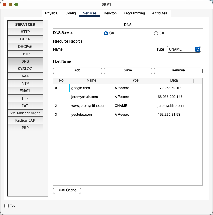
DNS
- Configure the following DNS entries on SRV1:
- google.com = 172.253.62.100
- youtube.com = 152.250.31.93
- jeremysitlab.com = 66.235.200.145
- www.jeremysitlab.com = jeremysitlab.com
This part is easy. Just configure SRV1’s DNS service like this.
- Configure all routers and switches to use domain name jeremysitlab.com and use SRV1 as their DNS server.
This will be the same on every device. Copy and paste the following:
! All routers and switches

ip domain name jeremysitlab.com
ip name-server 10.5.0.4
NTP
- Configure NTP on R1:
- Make R1 a stratum 5 NTP server.
- R1 should learn the time from NTP server 216.239.35.0.
- NOTE: NTP takes a LONG time to sync, especially in Packet Tracer. After making the configurations, you can move on – don’t wait for the devices to sync.
NTP is overlooked (at least by me) but also pretty simple to configure. You can configure devices as servers or clients, but you can also configure multiple NTP server sources. A smart thing to do is configure two external NTP servers for redundancy, but also configure a higher stratum internal NTP server in case they go down. Wendell Odom says it better than I can.
- Establish an association with the NTP servers per the ntp server command.
- Establish an association with your internal clock using the ntp master stratum command.
- Set the stratum level of the internal clock (per the ntp master {stratum-level} command) to a higher (worse) stratum level than the Internet-based NTP servers .
- Synchronize with the best (lowest) known time source, which will be one of the Internet NTP servers in this scenario.1
! R1

ntp server 216.239.35.0
ntp master 5- All Core, Distribution, and Access switches should use R1’s loopback interface as their NTP server.
- Clients should authenticate R1 using key number 1 and the password ccna.
You can use keys to authenticate NTP servers. Not on the test, but nice to know.
! R1
ntp authentication-key 1 md5 ccna
ntp trusted-key 1

! Switches
ntp authentication-key 1 md5 ccna
ntp trusted-key 1
ntp server 10.0.0.76 key 1
SNMP
- Configure the SNMP community string SNMPSTRING on all routers and switches. The string should allow GET messages, but not SET messages.
Simple Network Message Protocol (SNMP) creates a db of stats of devices in a network. You can use it to poll configs.
! All devices

snmp-server community SNMPSTRING ro
Syslog
- Configure Syslog on all routers and switches:
- Send Syslog messages to SRV1. Messages of all severity levels should be logged.
- Enable logging to the buffer. Reserve 8192 bytes of memory for the buffer.
! All devices

logging 10.5.0.4
logging trap debugging
logging buffered 8192
FTP
- Use FTP on R1 to download a new IOS version from SRV1:
- Configure R1’s default FTP credentials: username cisco, password cisco.
- Use FTP to copy the file c2900-universalk9-mz.SPA.155-3.M4a.bin from SRV1 to R1’s flash drive.
- Reboot R1 using the new IOS file, and then delete the old one from flash.
FTP is an easy way to move files around the network. This part is going to take a long, long time, so use the fast-forward button in Packet Tracer.
! R1

ip ftp username cisco
ip ftp password cisco
R1#copy ftp flash
Address or name of remote host []? 10.5.0.4
Source filename []? c2900-universalk9-mz.SPA.155-3.M4a.bin
Destination filename [c2900-universalk9-mz.SPA.155-3.M4a.bin]?
Accessing ftp://10.5.0.4/c2900-universalk9-mz.SPA.155-3.M4a.bin...
33591768 bytes copied in 146.062 secs (24147 bytes/sec)
R1#sh flash
System flash directory:
File Length Name/status
3 33591768 c2900-universalk9-mz.SPA.151-4.M4.bin
4 33591768 c2900-universalk9-mz.SPA.155-3.M4a.bin
2 28282 sigdef-category.xml
1 227537 sigdef-default.xml
[67439355 bytes used, 188304645 available, 255744000 total]
249856K bytes of processor board System flash (Read/Write)
R1(config)#do show ver
Cisco IOS Software, C2900 Software (C2900-UNIVERSALK9-M), Version 15.1(4)M4, RELEASE SOFTWARE (fc2)
...
File is transferred over. Now note the IOS version 14.1(4)M4. Let’s set R1 to boot the new image.
! R1

boot system flash:c2900-universalk9-mz.SPA.155-3.M4a.bin
do write
do reload
And now let’s check…
R1#show ver
Cisco IOS Software, C2900 Software (C2900-UNIVERSALK9-M), Version 15.5(3)M4a, RELEASE SOFTWARE (fc1)
Looking good! Now just clean up the old image.
R1#delete flash:c2900-universalk9-mz.SPA.151-4.M4.bin
Delete filename [c2900-universalk9-mz.SPA.151-4.M4.bin]?
Delete flash:/c2900-universalk9-mz.SPA.151-4.M4.bin? [confirm]
SSH
- Configure SSH for secure remote access on all routers and switches.
- Use the largest modulus size for the RSA keys.
- Allow SSHv2 connections only.
- Create standard ACL 1, only allowing packets sourced from Office A’s PCs subnet. Apply the ACL to all VTY lines to restrict SSH access.
- Allow only SSH connections to the VTY lines.
- Require users to log in with a local user account when connecting via SSH.
- Configure synchronous logging on the VTY lines.
! All devices

crypto key generate rsa
4096
ip ssh ver 2
access-list 1 permit 10.1.0.0 0.0.0.255
line vty 0 15
access-class 1 in
transport input ssh
login local
logging sync
do write
NAT
- Configure static NAT on R1 to enable hosts on the Internet to access SRV1 via the IP address 203.0.113.113.
Static NAT is kind of useless, but it is on the exam so let’s go over it. We need to specify which interfaces are inside and which interfaces are outside on R1.
! R1

int range g0/0-1
ip nat inside
int range g0/0/0,g0/1/0
ip nat outside
Next up, assign a static NAT address for SRV1.
! R1

ip nat inside source static 10.5.0.4 203.0.113.113
Check if SRV1 can ping outside the network. You’ll need to set its Name Server to 127.0.0.1 first.
C:\>ping google.com

Pinging 172.253.62.100 with 32 bytes of data:

Reply from 172.253.62.100: bytes=32 time<1ms TTL=252
Reply from 172.253.62.100: bytes=32 time<1ms TTL=252
Reply from 172.253.62.100: bytes=32 time<1ms TTL=252
Reply from 172.253.62.100: bytes=32 time<1ms TTL=252

Ping statistics for 172.253.62.100:
    Packets: Sent = 4, Received = 4, Lost = 0 (0% loss),
Approximate round trip times in milli-seconds:
Minimum = 0ms, Maximum = 0ms, Average = 0ms- Configure pool-based dynamic PAT on R1 to enable hosts in the Office A PCs, Office A Phones, Office B PCs, Office B Phones, and Wi-Fi subnets to access the Internet.
- Use standard ACL 2 to define the appropriate inside local address ranges in the following order:
- Office A PCs: 10.1.0.0/24
- Office A Phones: 10.2.0.0/24
- Office B PCs: 10.3.0.0/24
- Office B Phones: 10.4.0.0/24
- Wi-Fi: 10.6.0.0/24
- Define a range of inside global addresses called POOL1, specifying the range 203.0.113.200 to 203.0.113.207 with a /29 netmask.
- Map ACL 2 to POOL1 and enable PAT. Confirm that hosts can access the Internet by pinging jeremysitlab.com.
- Verify that Internet link failover works by disabling R1’s G0/0/0 interface and pinging again.
- You will need to remove and re-configure the OSPF default-information originate command for this to work. In real Cisco routers, you can configure the default-information originate always command that supports failover like this, but the command isn’t available in Packet Tracer.
- Re-enable G0/0/0 (and remove and re-configure default-information originate once again).
- Use standard ACL 2 to define the appropriate inside local address ranges in the following order:
PAT is what we now think of as NAT. It uses ports to dynamically route packets, so it also solves part of the IPv4 address exhaustion problem.
Start by making an ACL to match traffic we’re interested in translating.
! R1

access-list 2 permit 10.1.0.0 0.0.0.255
access-list 2 permit 10.2.0.0 0.0.0.255
access-list 2 permit 10.3.0.0 0.0.0.255
access-list 2 permit 10.4.0.0 0.0.0.255
access-list 2 permit 10.6.0.0 0.0.0.255
You can see your ACLs with a show command.
R1(config)#do show acc
Standard IP access list 1
    10 permit 10.1.0.0 0.0.0.255
Standard IP access list 2
    10 permit 10.1.0.0 0.0.0.255
    20 permit 10.2.0.0 0.0.0.255
    30 permit 10.3.0.0 0.0.0.255
    40 permit 10.4.0.0 0.0.0.255
    50 permit 10.6.0.0 0.0.0.255
Now let’s make a NAT pool and map the ACL we created earlier.
! R1

ip nat pool POOL1 203.0.113.200 203.0.113.207 netmask 255.255.255.248
ip nat inside source list 2 pool POOL1 overload
That’s all for PAT, let’s confirm from PC1.
C:\>ping google.com

Pinging 172.253.62.100 with 32 bytes of data:

Reply from 172.253.62.100: bytes=32 time<1ms TTL=252
Reply from 172.253.62.100: bytes=32 time<1ms TTL=252
Reply from 172.253.62.100: bytes=32 time<1ms TTL=252
Reply from 172.253.62.100: bytes=32 time<1ms TTL=252

Ping statistics for 172.253.62.100:
    Packets: Sent = 4, Received = 4, Lost = 0 (0% loss),
Approximate round trip times in milli-seconds:
    Minimum = 0ms, Maximum = 0ms, Average = 0ms
Looks like we can send and receive traffic from outside our gateway. Nice!
Now shutdown R1’s outside facing interfaces one at a time to make sure HSRP is doing its job, then repeat this test. Jeremy’s lab instructions mention that you need to remove and re-configure OSPF default-originate, but in my exercise this wasn’t necessary.
LLDP
- Disable CDP on all devices and enable LLDP instead.
- Disable LLDP Tx on each Access switch’s access port (F0/1).
! Non-Access Devices

no cdp run
lldp run

! Access Switches

no cdp run
lldp run
int f0/1
no lldp transmit
That’s all for this part (finally!) Don’t forget to copy run start, and see you for part 7.
- Odom, Wendell. “Chapter 9: Device Management Protocols” in CCNA 200-301: Official Cert Guide: Vol 2, 188 ↩︎